Blog

Zhejiang Balford Mechatronics Co., ltd focus on difficult stamping & deep drawing. Main product: motor housing and difficult custom deep drawn stampings.

  • What are the technical requirements for the custom processing of hardware chassis shells?

    By : Categories : Blog,Techniques Comment: Comments Off on What are the technical requirements for the custom processing of hardware chassis shells?

    Not only that, but the chassis also needs to be resistant to vibration. Stamping resistance, corrosion resistance, dust-proof, waterproof, radiation-proof and other properties ensure the stable and reliable operation of the equipment.

    2. With excellent performance and safety protection facilities, it is easy to operate, install and maintain, and ensure the safety of operators.

    3. Strain in production, assembly, debugging and packaging and transportation.

    4. It should meet the requirements of standardization, normalization and serialization.

    5. Beautiful appearance. Applicable, color coordinated.

    In the current era, the chassis has become an indispensable hardware product in the computer industry. Various styles of cabinets can be seen in major computer rooms. With the continuous development of today’s computer industry, the functions embodied by the cabinets are also getting bigger. Cabinets are generally used in network wiring rooms, floor wiring rooms, central computer rooms, data computer rooms, network cabinets, control centers, monitoring rooms, monitoring centers, etc.

    2. What are the types of chassis shell materials?

    The following Zhejiang Baifudu Electromechanical editor mainly introduces the common computer case materials for you. Let’s take a look!

    1. Acrylic side through case

    The transparency of the acrylic sheet is excellent, and the light transmittance of the colorless and transparent plexiglass sheet can reach 92%. In addition, the acrylic sheet also has flow weather resistance and strong adaptability to the natural environment. Long-term sunshine, wind and rain will not make it change. The acrylic side lens can see the use of the hardware inside the case. If the accessories inside the case have lighting effects, the color that comes out will be a different feeling.

    2. Sound absorption and noise reduction chassis

    The so-called active noise reduction is no longer blindly increasing the thickness of the board to passively and inefficiently block the noise, but adding high-density suction cotton to actively absorb the noise, eliminating a large part of the noise before it is transmitted to the chassis board, thereby enhancing the noise reduction effect. The material of the sound-absorbing cotton not only has a good sound-absorbing effect, but also has good heat dissipation. With several large-sized silent fans, it really kills two birds with one stone.

    3. Glass side transparent case

    Different from ordinary glass, tempered glass is generally used in the glass side see-through case, which forms compressive stress on the glass surface. When the glass is subjected to external force, it first offsets the surface stress, thereby improving the bearing capacity. Compared with ordinary acrylic and plastic side panels, the side panels made of tempered glass have stronger light transmittance, so after building a light pollution platform, the visual effect of tempered glass chassis is better, and the abrasion resistance of tempered glass is better. It should also be stronger than acrylic. After a period of use, it will not be scratched like acrylic, which will affect the appearance. In addition, due to the large weight of the tempered glass, it can effectively stabilize the body and prevent the chassis from resonating. Therefore, tempered glass is more and more popular with chassis manufacturers and DIY players.

    4. Aluminum chassis

    Aluminum chassis often have the characteristics of excellent heat dissipation, electromagnetic shielding, and light material. The chassis of this material is very textured whether you look at it or touch it, but the price of aluminum chassis is very expensive, and the appearance of the chassis is very high. Changes are also less. Compared with the steel plate, the strength of the aluminum plate is lower, especially the upper plate, the side plate, and the side plate that is not installed on the chassis. If you accidentally step on it, it will leave irreparable dents.

    5. Plastic case

    Compared with metal materials, one advantage of plastic materials is that shaping and coloring will be very simple, which increases the look and feel of the chassis. However, the quality is also clear. The plastic material not only has low strength and cannot absorb electromagnetic radiation, but also is more prone to scratches and difficult to maintain.

    6. SECC chassis

    SECC is electrolytic lead galvanized steel sheet. It is a stamping material, that is, a zinc layer is plated on the surface of the cold-rolled sheet, and the surface is smooth and gray. Anti-rust and corrosion-resistant, but the price is relatively high. The general plate thickness is between 0.4~3.2mm. SECC material is more common in big brand computer case manufacturers, and the price is more expensive than hot-dip galvanized sheet. So, we can see this material in high-end gaming cases or server cases.

    Read More →
  • What are the application scope of metal stamping products?

    By : Categories : Blog,Industry Comment: Comments Off on What are the application scope of metal stamping products?

    1. Application scope of metal stamping products

    1. Stamping parts for daily necessities: mainly to do some handicrafts, such as tableware, kitchen utensils, faucets and other daily hardware.

    2. Electrical device stamping: The electrical stamping factory is a new industry developed with the development of electrical appliances. Such manufacturers are mainly concentrated in the South.

    3. Stamping in the automotive industry: For example, the body, frame, rim and other parts are stamped. Mainly deep drawing, mainly concentrated in automobile factories, tractor factories, aircraft factories and other large factories.

    4. Stamping in the medical industry: It is necessary to assemble various precision medical devices, and the stamping in the medical industry develops rapidly.

    5. Special stamping enterprises. For example, the stamping of aerospace components belongs to this category, but these process plants also belong to some large factories.

    Metal stamping parts have the advantages of simple operation, easy automation, and accelerated production efficiency. They are widely used in many industries and play an indispensable role.

    Read More →
  • What aspects should metal stamping parts processing plants pay attention to in the design?

    By : Categories : Blog,Techniques Comment: Comments Off on What aspects should metal stamping parts processing plants pay attention to in the design?

    Generally speaking, the process of producing auto parts in metal stamping parts processing plants includes: stamping, cleaning, welding, degreasing, cleaning, electrophoresis, etc.

    1. When designing the structure and shape of auto parts, it is best to adopt a simple and reasonable structure, and at the same time minimize the number of machined surfaces and processing area.

    2. The materials used in automotive metal stamping parts must not only meet the technical requirements of product design, but also meet the stamping process requirements of stamping parts processing plants, as well as the processing requirements of cutting, electroplating, cleaning and other processes after stamping.

    3. In the forming process, in order to facilitate the improvement of stamping deformation and the quality of the parts, the material should have good plasticity, a large plate thickness direction coefficient, a small plate plane direction coefficient, and a small yield strength and elastic modulus ratio of the material. Regarding the separation process, the material does not need to have good plasticity, but it should have a certain plasticity. The better the plasticity of the material, the easier the separation will be.

    Read More →
  • How to reflect the processing quality of metal stamping parts?

    By : Categories : Blog,Industry Comment: Comments Off on How to reflect the processing quality of metal stamping parts?

    1. What are the aspects of the processing quality of metal stamping parts?

    1. Chemical analysis, metallographic examination

    Analyze the content of chemical elements in the material, determine the particle size level and uniformity of the material, evaluate the level of free cementite, banded structure and non-metallic inclusions in the material, and inspect the material for defects such as porosity.

    2. Material inspection

    The materials for stamping parts are mainly hot-rolled or cold-rolled (mainly cold-rolled) metal sheet and strip materials. The raw materials of metal stamping parts should have quality certificates to ensure that the materials meet the specified technical requirements. When there is no quality certificate or other reasons, manufacturers of metal stamping parts can select raw materials for re-inspection as needed.

    3. Formability test

    Perform bending test and cupping test on the material to determine the work hardening index n value and plastic strain ratio r value of the material. In addition, the test method for the formability of the steel plate can be carried out according to the provisions of the formability and test method of the thin steel plate.

    4. Hardness test

    The hardness test of metal stamping parts adopts Rockwell hardness tester. Small stampings with complex shapes can be used for small test planes and cannot be tested by ordinary desktop Rockwell hardness testers.

    5. Measurement of other performance requirements

    Determination of electromagnetic properties of materials and adhesion to coatings and coatings.

    The technical requirements for processing metal stamping parts are shared with you here. In addition, it should be noted that the accuracy and surface condition of hot metal stamping parts are lower than those of cold metal stamping parts, but they are still better than castings and forgings, and the amount of machining is less.

    Read More →
  • What are the positioning benchmarks for stamping processing?

    By : Categories : Blog,Techniques Comment: Comments Off on What are the positioning benchmarks for stamping processing?

    1. Principles of selection of fine benchmarks

    1. The principle of datum coincidence: The design datum of the machined surface should be selected as the precise datum as much as possible, which can avoid the positioning error caused by the misalignment of the datum.

    2. The principle of mutual reference: when the positional accuracy between the two machined surfaces on the workpiece is relatively high, the method of repeated machining of the two machined surfaces as a reference to each other can be used.

    3. Self-base principle: some surface finishing processes require small and uniform machining allowances, and the machined surface itself is often used as the fine base.

    4. Unified datum principle: as many surfaces as possible on the workpiece should be machined with the same set of fine datums as much as possible to ensure the relative positional accuracy between the machined surfaces.

    The above four principles for selecting rough benchmarks can sometimes not be taken into account at the same time, so the main decision should be made.

    2. Principles of selection of rough benchmarks

    1. A rough benchmark should be used in one process of workpiece processing. Whether the rough benchmark is selected correctly or not is not only related to the processing of the first process, but also has a significant impact on the entire process of workpiece processing.

    2. The principle of rationally allocating machining allowances: Considering ensuring that the machining allowances of important surfaces are uniform, important surfaces should be selected as rough benchmarks.

    3. The principle that rough benchmarks should not be reused in general.

    4. The principle of easy clamping: In order to stabilize the positioning of the workpiece and the clamping is reliable, the selected rough datum is required to be as smooth and clean as possible. Forging flashes, pouring riser cuts or other defects are not allowed, and there must be enough support area.

    Read More →
  • How to assemble the stamping continuous die?

    By : Categories : Blog,Industry Comment: Comments Off on How to assemble the stamping continuous die?

    1. How to install the stamping die?

    1. Confirm whether the blanking hole of the die and the blanking hole of the pad are consistent.

    2. After the upper and lower dies are assembled, put them on the lower table, and ensure that the datum plane of the punch and the datum plane of the mold are parallel.

    3. The lower mold should be completely fixed, and the upper mold should be lightly fixed in advance.

    4. Test the slider on the punching machine for 20-30 times. After confirming that the upper and lower dies are in complete agreement, tighten the upper dies.

    5. The bite component of the punch and concave die is combined with the lower die stopper of the die to adjust the height of the slider on the punch press.

    6. Use the test punch of the sealing paper to confirm its cutting condition. If it is not uniform, check the installation state of the mold again. If the consistency cannot be achieved, it is necessary to confirm the parallelism of the punch slide and the lower table of the punch.

    7. Adjust the material feeding length and feeding time. (If a scrap cutter is attached, the length of the material to be fed can be confirmed by the length of the cut scrap)

    8. Comprehensive operation for 3-5 minutes. During this period, oil should be filled between the guide column and the bushing, and it should be confirmed whether there is any abnormality in the heat.

    9. Try on the selected material to be processed to confirm that there is no obstacle in the insertion.

    10. After the above work is completed, processing can be carried out. First, press down the first material positioning rod set on the side of the lower die, and feed the material until it touches the positioning rod. After insertion, the test punch is first hand-fed until the end of the final process.

    11. After confirming that there is no abnormality in the hand feeding type, close the switch of the punch feeding device. At this time, the feeding work needs to be carried out completely on the finished position.

    12. The punching die uses a single punching motion to confirm whether the feed is appropriate.

    2. What is the mold assembly to do?

    1. Select the assembly reference parts. When assembling, first select the reference part. The principle of selecting reference parts is determined according to the dependence of the main parts of the mold during processing. The main components that can be used as assembly reference parts are punches, punches, punches and punches, guide plates and fixed plates.

    2. Component assembly. Component assembly refers to the assembly work in which two or more parts are connected into a component according to the specified technical requirements before the final assembly of the mold. Such as the assembly of the mold base, the assembly of the punch and the concave mold and the fixed plate, the assembly of the parts of the unloading and pushing mechanism, etc. These components should be assembled according to the functions of each part, which will play a certain role in ensuring the assembly accuracy of the entire stamping die.

    3. Overall assembly. Final assembly is the process of combining parts and components into a complete stamping die. Before final assembly, the reference parts for assembly should be selected and the assembly sequence of the upper and lower dies should be arranged.

    4. Adjust the gap between convex and concave die. When assembling the mold, the uniformity of the gap between the convex and concave molds must be strictly controlled and adjusted. After the gap is adjusted, the screws and pins can be tightened. The methods for adjusting the gap between the convex and concave molds mainly include the light transmission method, the measurement method, the gasket method, the coating method, and the copper plating method.

    5. Inspection and debugging. After the stamping die is assembled. The assembly accuracy must be guaranteed, the specified technical requirements must be met, and the function of each part of the mold must be inspected in accordance with the technical conditions for mold acceptance. Test the mold under the actual production conditions, and adjust and correct the mold according to the conditions of the test mold production parts. When the mold test is qualified, the mold processing and assembly are basically completed.

    Read More →
  • 6 considerations for stamping continuous die design

    By : Categories : Blog,Industry Comment: Comments Off on 6 considerations for stamping continuous die design

    1. Punching waste should not be ejected

    When designing continuous molds, the discharge of scrap is as important as the conveying of the coil. The timely and reliable discharge of punching waste from the mold is the basis for ensuring the normal production efficiency of continuous molds. For fine blanking dies, punching waste cannot leak from the die hole, but can only be ejected from the die surface.

    2. The depth of the hole for the float pin of the discharge plate in the continuous die should be reasonable

    When the part material is thin, the height position of the floating pin should match the depth of the breakaway hole of the stripper. If the escape hole of the stripper plate is too deep, the material will be bent upwards under the action of the compression spring force, and the material will not be able to be fed normally; if the escape plate of the stripper plate is too shallow, the material will be cut off. Therefore, the depth of the hole for the floating pin of the stripper plate in the continuous mold should be reasonable.

    3. The continuous die should not have positioning devices such as stoppers and side blades

    For the continuous die stamping workpiece, it is necessary to solve the problem of accurate positioning of the strip material and ensure that the step distance of the continuous die is consistent so that qualified parts can be punched out. Commonly used positioning devices include fixed baffle pins, guide plate pins, guide plates, and side blades.

    Fourth, the position of the side edge in the continuous die cannot be ignored

    Side edge positioning can accurately control the step distance and has high positioning accuracy, but it needs to cut one or both sides of the material, resulting in waste and waste. When using the side edge distance, the side edge position should be appropriate.

    5. The shape of the side edge in the continuous die cannot be ignored

    There are three side edge shapes in continuous die: rectangular flat side edge, L-shaped side edge and concave side edge. The rectangular flat side edge is easy to make, but it is easy to produce burrs. The L side edge affects the feeding, and the concave type does not affect the feeding, but it increases the manufacturing difficulty of the side edge.

    Six, the continuous mode guide pin should not be too long

    In order to control the feeding step, continuous molds need better positioning devices. Among them, the guide pin is a precise positioning method widely used in continuous molds. It should be noted that the length of the guide pin should not be too large, and the length of the guide hole should not be too large, otherwise it will break due to insufficient rigidity.

    Read More →
  • Design principles of precision stamping die structure

    By : Categories : Blog,Techniques Comment: Comments Off on Design principles of precision stamping die structure

    1. Design principles of precision die structure

    1. According to the production batch of stamping parts, determine whether to use a simple die structure or a complex die structure. Generally speaking, a simple die structure has a short life and low cost, and a complex die structure has a long life and high cost. Therefore, if the number of stamping parts is small, it is more suitable to use a simple die structure. Larger quantities are more suitable for conventional die structures with longer service life.

    2. The accuracy level of the stamping die is determined according to the size requirements of the stamping parts. If the dimensional accuracy and section quality of the stamping parts are high, the precision stamping structure should be used, and the stamping parts with general precision requirements can use the ordinary stamping structure.

    3. Select the type of stamping die according to the capability of the existing equipment. For example, when drawing workpieces, a double-action die structure is much better than a single-action die structure.

    4. The type of unloading device in the die structure is selected according to the thickness of the stamping plate. For example, when blanking thick plate workpieces, if the requirements for surface straightness and sharpness are not high, a fixed unloading device can be selected. Suitable for selection.

    5. Select the mold type according to the technical conditions and economy of mold manufacturing. For example, when the technical requirements of die manufacturing are low, a simple die stamping structure should be designed as much as possible. When the variety of mold equipment is complete and the machining accuracy is high, in order to improve the service life of the mold and achieve mass production, a more complex precision mold stamping structure should be selected.

    Designers should consider a variety of factors when choosing a die structure. Because simple stamping dies and general traditional stamping dies have their own advantages and limitations. This requires analysis and comparison to make the selected stamping die structure mode as reasonable and reliable as possible.

    Read More →
  • Metal stamping continuous die layout technology

    By : Categories : Blog,Industry Comment: Comments Off on Metal stamping continuous die layout technology

    1. Design principles of continuous stamping layout drawing

    Before blanking of flat blanking parts (including flat blanks of various forming stamping parts – the same below), in order to save materials, economical and reasonable arrangement is carried out on plates, strips, strips and coils to obtain the best samples and achieve the best possible results. Possible high material utilization. In the cold stamping process design and die design, this is an important and technical work; in the cold stamping die structure design, the stamping part drawing, stamping process and its sample drawing are the main basis.

    In the known professional publications, the layout of single-station blanking dies and composite die-stamping parts is introduced in detail, and the layout of multi-station continuous die-stamping parts is not involved.

    The layout drawing of multi-station continuous stamping parts should fully explain the stamping process and the sequence of stamping steps, and indicate the feeding distance, the specific data of edge extension and edge overlap, the feeding method between stations, and all stamping processes and deformations of stamping parts. and separation process.

    Die selection, structural design, stamping material utilization η, stamping productivity are closely related to the production cost of stamping parts, but also affect the quality of stamping parts and die life. The layout should fully consider the material supply and the production conditions of the stamping equipment. On the basis of ensuring the stamping quality, efforts should be made to make the stamping die have better structure, better operational safety and die technology, and comprehensively analyze the various factors that affect the layout. Factors, compare multiple schemes, and choose the best layout.

    Before the die stamping design begins, the die stamping drawing and layout drawing should be analyzed to understand its main technical requirements and stamping difficulties, and lay the foundation for the die stamping structure design according to the rationality of the die stamping process and possible problems.

    Among the many single-process dies, only blanking dies and single-station composite dies need to design layout drawings. That is to say, when blanking (blanking) flat blanks and forming stampings to develop flat blanks, nesting is required. And most of them are conventional nesting methods with scrap blanking along the edge, and most of them can only achieve less scrap blanking. Regardless of the layout method used, the rationality and advantages and disadvantages of layout are generally measured by the material utilization rate.

    The layout of continuous die-stamped parts is different from the above. Material utilization η is not the most important and only criterion for measuring the quality of nesting.

    For the layout of continuous die stamping parts, it is necessary to analyze the stamping process, reasonably design the stamping process and the sequence of the stamping process, fully consider the characteristics of the continuous stamping process and the needs of the stamping structure design, and pay attention to the feeding and inter-station feeding methods. selection and design of positioning systems.

    Therefore, the layout of continuous die stamping parts is based on the design of continuous stamping process steps, with the core of ensuring the quality of stamping parts and the accuracy of size and shape, and the sequence arrangement of stamping steps and the selection of the feeding method between stations are as follows: Pilot, for the purpose of die selection and structural design, the basic principles that should be followed are as follows: 

    (1) It is beneficial to choose a simpler type and structure of punching die, and its operation is safe and the quality of punching parts is good.  

    (2) The manufacturing process of the die is good, the grinding is convenient, the molding cycle is short, and the cost of molding and repairing is low.

    (3) The plate utilization rate η value is high.  

    (4) The mold life is longer.  

    (5) The stamping efficiency is higher, and the production cost of stamping parts is lower.

    Among the above five articles, article (1) is the primary one.

    Sometimes it is impossible to have both, the user’s requirements and delivery time should be considered first, and other terms can be appropriately relaxed. In many cases, higher material utilization η tends to complicate the structure of the die, making the die more difficult, and even difficult to manufacture with the existing die-making equipment and technical level, no matter how good the layout and the higher the η value. , and must also be abandoned; some would rather reduce the utilization rate of the plate η to obtain better molding processability, shorter molding cycle, and higher mold life.

    2. Selection of layout form and its relationship with die type and structure

    For blanking dies and composite dies with only one station, the layout methods of flat blanking and various forming blanks on plates, strips, strips and coils are usually: single row, straight row, Single row oblique row; double row parallel row, double row head-to-head row, double row head-to-head oblique row; multi-row row, staggered row and mixed row, etc.

    Different nesting methods obtain different material utilization rates, and the choice of different nesting methods should first consider the size and shape accuracy of the punching parts, and then decide to choose the appropriate type of punching die and its structure.

    If the dimensional accuracy of punched parts is required to be above 1t10 level, the layout method with edge and overlap should be adopted; the dimensional accuracy of punched parts without overlap layout is poor, generally below 1t12 level, or even as low as 1t14 level. If the dimensional accuracy of the punching piece is as high as 1t9 or higher and the punching piece is required to be straight, a punching die with a sliding guide column die set with a spring-loaded stripper structure should be selected, and its layout should be given enough edge and overlap.

    According to the German Industrial Standard din1543, the cold stamping steel plate is classified according to the thickness t: t<3mm is a thin plate.

    In the production of products in the instrumentation and electronic industries, ultra-thin foil stamping parts with t≤0.3~0.1mm or even ≤0.1~0.05mm are often used, which brings many difficulties to stamping layout and die design.

    Because the edge of the nesting, the width of the overlapping edge and the size of the blanking gap all increase or decrease with the thickness t of the blanking material.

    When t≤0.5mm, the width of the lap and edge should be greater than t so as not to be pulled into the die hole during punching, and to make it have sufficient strength and ensure that the lap frame has a good feeding rigidity; t= 0.3mm low carbon steel plate, according to the class I gap stipulated by gb/t16743-1997 “Blanking Gap” Internationally, 3%t can be taken as the unilateral gap of punching die c=3%×0.3mm=0.009mm, t=0.1mm then c=0.003mm, which is 3μm. And gb/t2854-90 international grade I sliding guide guide column die set stipulates the guide column guide sleeve matching clearance is 0.010 ~ 0.016mm. Therefore, when the above-mentioned ultra-thin material is punched and continuously punched, special attention should be paid to selecting a suitable layout method and designing a reasonable and precise mold structure, otherwise it will be difficult to complete the punching of such punching parts, and it is impossible to meet the requirements. Dimensional and geometric accuracy.

    For continuous stamping and forming of ultra-thin punching parts with t<0.5mm, the width of the overlapping edge and the edge of the layout can be the same, and it can be appropriately enlarged according to the needs of the die structure design. In terms of the selection of die structure type, it is recommended to select the guide column die frame elastic pressure unloading guide die, and it is best to install the elastic pressure guide plate on the guide column and install a small guide column on the discharge plate (guide plate) to ensure the elastic pressure discharge. The guide plate type punching die has precise guidance and improves the punching accuracy of the punching die; the coaxiality and position of the punching group holes put forward higher requirements on the accuracy of the layout and feeding distance and the feeding and positioning of the punching die. Special attention should be given to layout.

    Ultra-thin punching parts with material thickness t≤0.1mm, especially complex-shaped punching parts formed by multiple stations and one die, should not use multiple rows of oblique rows, facing rows and turning punches, and it is even more unsuitable to use mixed rows. Otherwise, the frame will be easily deformed, broken, or even pulled into the die during feeding, which will affect production, increase scrap products, and damage the mold; for medium and heavy plate punching with a material thickness of t≥3mm, cutting and stacking layout is not recommended. , t ≥ 4.75mm, it is not recommended to use nesting and cutting layout. Otherwise, it will bring difficulties to the structural design of the mold.

    For high-precision foil stampings with dimensional accuracy ≤±0.01mm and material thickness t≤0.1mm, especially for stampings with complex shapes with a precision higher than 1t9, it is recommended to use a ball-guide-pillar die-base elastic-pressure unloading guide-type die structure.

    Layout drawing design points The layout drawing design of single-station blanking die and compound die is to expand the shape of flat blank according to flat blanking parts and three-dimensional forming parts, and repeatedly arrange them on strips and strips to ensure the quality of punching parts. In the case of production efficiency and process requirements, the die structure is simpler, the mold making is more convenient, and the highest possible material utilization rate is the criterion, and a better layout method is selected. Under normal circumstances, the shape and size structure of the blanking parts determine the type of layout, and most of them need to use the traditional layout method with edge and overlap to carry out blanking with waste.

    According to many years of practical experience, for the design of the layout drawing of single-process blanking and composite punching and single-station integrated composite stamping, it can be considered as a single blanking of flat blanks and three-dimensional forming parts. Compared with single punching die, the layout of continuous die punching parts is much more complicated. The layout should ensure the smooth implementation of the continuous punching process and obtain the highest possible η value. The operation is safe, the efficiency is high, there are many influencing factors, and the requirements are high. The steps and key points are as follows:

    (1) After a detailed process analysis of the stamping parts, the feasibility of continuous stamping and one-die forming of the stamping parts is studied, and a number of stamping process schemes are proposed for comparison, and the layout is implemented after selecting the best ones.

    (2) The shape, size and accuracy of the stamping directly affect the continuous stamping process and the sequence of the steps. When laying out the layout, the manufacturability of the continuous stamping and the needs of the die structure design should be considered, and attention should be paid to the sequence of the steps and the arrangement of the stations. The following points:

    a. The holes in the group of holes on the punching piece whose hole spacing accuracy is required to be above 1t10 or the hole spacing tolerance value is less than 0.01mm should be punched out in one or two adjacent stations;

    b. If the hole wall and hole edge of the punched part are smaller than the material thickness t or less than 2mm, they should be punched out in two stations in steps to enhance the strength of the die and expand the installation position of the punch on its fixing plate;

    c. For the coaxiality and position of the group holes, the requirements are very high, and the tolerance is less than 0.01mm. The relevant holes can be punched out at one time or in two adjacent stations. The parts that require smooth punching and punching should be concentrated. Implemented at one or two stations;

    d. If the shape of the punched part and the size tolerance of the formed part are very strict, the overall blanking can be considered and then bent or deep drawn; if the size of the local boss or notch of the punched part is strict, it can be punched separately by multiple stations. post splicing;

    e. For small and complex shaped stampings with large output, multi-station continuous stamping and one die should be used as much as possible to improve the quality and efficiency of stampings; 

    f. The dimensional accuracy requires high-precision punching parts above 1t10. When laying out samples, the number of steps should be minimized to prevent the number of stations from being too large, the accumulation of feeding errors will be large, and the punching accuracy will be reduced. Partial fine punching, upsetting extrusion, flattening, etc. should be Arrange special work stations; 

    h. For punching parts with complex multi-directional bending, lateral punching and incision that need to be punched with lateral force, consideration should be given to using wedge drive transverse punching to form after plane punching, incision or before blanking. Precision and Efficiency.

    (3) Considering the requirements of the die structure design and the required position of the stamping deformation, set up the necessary neutral station, and increase the installation position of the punch on the fixed plate; Surface area, an empty station should also be added to increase the wall thickness of the die.

    3. Layout type and method of continuous die stamping

    According to the characteristics of the continuous die stamping process, the same feeding method of the station, whether the layout has overlapped edges, and the method of removing process waste, the layout of the continuous die stamping parts can be summarized into the following types and layout methods:

    1. Slitting and combining layout

    Each station punches and forms a part of the punching piece respectively. Each station is relatively independent and independent of each other. Its relative position is controlled by the die, and finally combined into a complete and qualified punching piece, see Figure 1a), b), f), j).

    2. Piece and cut combination layout

    The inner hole and shape of the punching piece, even a complete blanking line of any shape, are punched separately by several stations, and finally assembled into a complete punching piece. Although it is similar to the slitting combination, it is not the same. The combination of each station and the cutting edges are related to each other, and the interface parts must overlap, which increases the difficulty of mold making.

    3. Cutting edge layout

    The complex shape of the side of the punched piece is obtained by the method of punching along the edge, that is, the cutting edge layout. When the length l of the punching edge in the feeding direction is equal to the feeding distance s, that is, l=s, the punch can replace the side edge and undertake the task of cutting the edge of the fed raw material. This type of side punch is commonly referred to as a forming side edge. Because jb/t-76481-94 has few standard side edge varieties and limited size specifications, the maximum cutting edge length is only 40.2mm. When the feeding distance s>40.2mm, only non-standard side edges can be used.

    Another disadvantage of using a standard side edge is that it is necessary to cut a certain width of material on the side of the raw material to form an incision with a length equal to the feeding distance. Positioning the feeding raw material increases the process waste and reduces the η value by 2% to 3%. %. Using the side punch to cut the edge can not only complete the blanking of any complex shape of the side profile of the punching piece, but also realize the limit of the feeding distance of the raw material, instead of the standard side edge, which serves multiple purposes.

    4. Cut and overlap the layout

    For slender and thin blanking parts, long blanking parts with complex contours to be blanked at the part connected to the lap edge, can obtain high-quality and high-yield effects by laying out the lap edge, which can avoid slender blanking parts Disadvantages such as distortion and difficult unloading. The more typical punching parts are instrument hands, watch second hands, etc. The above cutting edge layout is used, and the effect is very good. For the convenience of molding, sometimes the edge is enlarged to facilitate blanking, and the edge is left on the raw material as a punch. The pieces are finally cut and separated.

    5. Combined punching and nesting along edge and overlapping edge

    Step by step punching the edge and lap by sub-station, to obtain the layout of the formed punching blank and punching and forming, which is called the combined punching layout of the edge and the lap. The process wastes are washed away at each station, and the punched parts are left on the raw materials and gradually formed until the final station is separated. This type of layout can keep the stations on the same plane and arrange them in a straight line along the feeding direction. The raw materials are used to carry the workpieces into place between the stations. The mold structure is simple, and the operation is convenient and safe.

    6. Nesting layout

    Use the structural waste of the inner hole of the large-sized punching piece to punch the smaller-sized punching piece of the same material in the special station of the same set of continuous molds, that is, the nesting layout.

    Under normal circumstances, the small-sized punching parts in the inner hole are punched first, and the large-sized punching parts are often punched out at the last station.

    The nesting of gaskets with a single-station composite blanking die is a typical nesting layout that has been known for a long time. For the nesting layout of multi-station continuous blanking parts, because the upper and lower stations have no overlapping edges, the coaxiality is required to be high, and the feeding distance must be small to ensure the size and shape accuracy of the nesting blanking parts.

    7. Layout layout

    Using the process waste of the punched parts and the structural waste connected along the edge, the punching parts of the same material are spliced ​​and punched together, that is, the layout is cut out. The difference from nesting and layout is that stenciling is to make the best use of process waste or excess edge and overlap, as well as the outer edge structure waste generated due to the complex shape of the punched parts and the large difference between convex and concave. The punching material is the same. Various punching pieces. When laying out samples, make full use of the convex and concave parts of the shape of the punching parts, and insert forks into each other to make full use of the raw materials.

    No lap layout and no-waste blanking Since most of the continuous die-stamping parts use edge and lap layout, only blanking with waste can be carried out. If the layout without edge and edge can be carried out, and the blanking part has no structural waste, it can be blanked without waste. Completely scrap-free blankings that truly achieve 100% or near 100% sheet utilization are rare. Any punching that can be used for layout without overlapping can be punched with less waste.

    In order to implement the blanking of blanking parts with no waste and less waste, it is first necessary to carry out the layout of blanking parts without overlapping edges.

    There are certain conditions and methods for the implementation of no-overlap nesting. In addition to the above-mentioned continuous die-punching parts, which can be used for layout without overlapping edges and blanking with no waste or less waste, single-process punching dies and single-station composite punching dies can also do the same.

    4. Non-linear feeding continuous composite die-stamping method

    The feeding direction of most continuous molds is carried out along a straight line on the same plane, and the feeding of each station is carried out by feeding raw materials. For this reason, the punched parts are always kept on the raw materials with lap edges for stamping processing at each station. The finished punching piece connected with the lap edge cannot be separated from the raw material until the processing is completed to the last station. For some punching parts with large flange heights, large drawing heights and complex shapes that require multi-directional force bending, it is often necessary to blank them as a whole and then form them on another set of punching dies.

    Otherwise, the punched part can be taken out from the die cavity because the die needs to have a large opening height. If the conventional continuous die is used to arrange the stations in a straight line on the same plane along the feeding direction, it will be difficult to design the die structure.

    This type of punching piece is formed by a multi-station continuous die, and its layout method is completely different from the above-mentioned conventional continuous die layout. The blanking blank is pushed to the forming station at a certain angle to the feeding direction of the raw material, and is bent or deep drawn. Make the stations of the die arranged in an L shape, and the stations are not on the same plane

    With the rapid development of modern stamping technology, the continuous improvement of stamping mechanization and automation, and the improvement of stamping safety production requirements, continuous dies of this type of structure will be increasingly widely used.

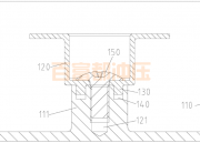
    The three-station continuous composite die for lifting ring punching parts, the first station punches rectangular holes, the second station is blanking, bending and compound punching, and the third station is a feeding system driven by the wedge of piece 8. After the curved workpiece at the second station is pushed into place along the bending core piece 12, the two sets of 13 cam drive mechanisms are used to exert force opposite and perpendicular to the feeding direction to push a pair of forming die pieces 17, and the stamping workpiece is finally formed. The die has both the action characteristics of a continuous die and the function of a composite die. Since the second to third stations are formed by separating the workpiece from the raw material, it is not realistic to call the progressive die;

    Calling a continuous die ignores the function of the second station compound stamping and the separation and deformation of the entire die and the characteristics of the compound stamping, so it is more appropriate to name it a continuous compound die.

    The continuous composite die adopts staggered double rows and straight rows. After the overall blanking, the unrolled blanks are pushed to both sides and bent at the third station. The production efficiency is high and the punching quality is good. This type of automatic or semi-automatic continuous compound die is safe to operate, and will be used more and more with the diversification of coil supply varieties and specifications.

    Read More →
  • Appearance acceptance criteria for metal stamping dies

    By : Categories : Blog,Techniques Comment: Comments Off on Appearance acceptance criteria for metal stamping dies

    1. Appearance acceptance criteria for metal stamping dies

    1. The content of the mold nameplate is complete, the characters are clear, and the arrangement is neat.

    2. The nameplate should be fixed where the die foot is close to the template and the reference angle. The nameplate is fixed reliably and is not easy to peel off.

    3. The cooling water nozzle shall not protrude from the surface of the mold base.

    4. The cooling water nozzle should be marked with in and out.

    5. The cooling water nozzle should be made of plastic block inserting water nozzle, and it should be selected according to the safety requirements of the customer.

    6. The cooling water nozzle should be machined with countersunk holes, the orifice chamfered, and the chamfers should be consistent.

    7. The marked English characters and numbers should be larger than 5/6, and the handwriting should be clear, beautiful, neat and evenly spaced 10mm below the faucet.

    8. The mold accessories shall not affect the lifting and storage of the mold. During the installation process, there are exposed oil cylinders, faucets, pre-reset mechanisms, etc. below, which should be protected by supporting legs.

    9. The installation of the support legs should be fixed on the mold base with screws through the support legs, and the excessively long support legs can be fixed on the mold base with the machined external thread columns.

    10. The size of the ejection hole of the mold should meet the requirements of the specified injection molding machine. Except for small molds, it cannot be ejected with just one center/center.

    11. The positioning ring should be fixed and reliable. The diameter of the positioning ring is 100mm and 250mm. The positioning ring is 10~20mm higher than the bottom plate. Unless otherwise requested by the customer.

    12. The size of the mold should meet the requirements of the specified injection molding machine.

    13. For molds required by the installation direction, the installation direction should be marked with an arrow on the front or rear template, and the word UP should be marked next to the arrow. The arrow and the text are both yellow, and the height of the word is 50 mm.

    14. The mold should be easy to hoist and transport. Do not disassemble the mold parts during hoisting, and the lifting ring must not interfere with the faucet, oil cylinder, pre-reset rod, etc.

    15. The surface of the mold base shall not have defects such as pits, rust, excess rings, water vapor in and out, and oil holes that affect the appearance.

    2. Technical requirements for the appearance of stamping parts

    Stamping parts have the following technical requirements in the process of production, storage and transportation:

    1. Shape and size: The shape and size of the stamping part need to conform to the stamping part product drawing and technical documents.

    2. Surface quality: In addition to punching, the surface condition of stamping parts should be consistent with the sheet material used. Slight bruising and small surface unevenness are allowed during the forming process, but it does not affect the next process and assembly. the quality of.

    3. Burr: Stamping parts that are often cut or punched will generally have burrs, and the allowable height of burrs can be in accordance with the provisions of EQY-85-88 “Burr Height of Stamping Parts”.

    4. Punching surface: the condition of punching surface is generally not specified;

    5. Heat treatment: stamping parts are generally not heat treated after stamping and welding;

    6. Supply status: The supply of stamping parts should ensure its basic quality status, in line with the stamping parts product drawing and inspection card.

    In addition, stamping parts also need to meet their unique anti-rust requirements: stamping parts circulating in the factory must ensure 15 days of anti-rust time.

    Read More →
  • The basic characteristics of stamping die processing

    By : Categories : Techniques Comment: Comments Off on The basic characteristics of stamping die processing

    First, the basic characteristics of stamping die processing 1. The requirements for machining accuracy are relatively high. A pair of molds is generally composed of a punch and a die base. Of course, it may also be a multi-piece splicing module. Therefore, the combination of the upper and lower molds, the inserts and the cavity. […]

    Read More →
  • Talking about the influence of the necking process in the processing of metal stamping parts

    By : Categories : Blog,Industry Comment: Comments Off on Talking about the influence of the necking process in the processing of metal stamping parts

    In the process of shrinking, the metal stamping material at the shrinking end slides into the die under the pressure of the punch to reduce the diameter and increase the wall thickness and height. It can be approximated that the deformation region is in a state of plane stress under positive pressure in both tangential and radial directions, and the tangential pressure is the main force. The radial compressive strain is the maximum strain, while the thickness and length directions are elongation deformation, and the deformation amount in the thickness direction is more than that in the length direction.

    Due to the action of tangential compressive stress, the billet is easily unstable and wrinkled during the shrinking process; at the same time, the wall of the non-deformed area is also prone to instability and deformation due to all the shrinking pressure. Therefore, preventing instability is shrinking. The main problem with the process.

    The ultimate deformation degree of the necking is mainly limited by the buckling conditions. The degree of deformation of the necking depends on the necking coefficient of the material. It is expressed by the total shrinkage coefficient ms:

    ms = d/D     where

    ms—total shrinkage coefficient, d—diameter after shrinkage; D—diameter before shrinkage.

    The size of the shrinkage coefficient is related to the mechanical properties of the material, the thickness of the material, the form of the mold, the surface quality, the edge of the shrinkage end of the part and the lubrication conditions. The comprehensive mouth coefficient of various materials can be obtained through the relevant information table.

    Read More →
  • What are the factors that affect the dimensional accuracy of metal stamping parts?

    By : Categories : Blog,Industry Comment: Comments Off on What are the factors that affect the dimensional accuracy of metal stamping parts?

    The dimensional accuracy of metal stamping parts refers to the difference between the actual size and the basic size of the stamping parts. The smaller the difference, the higher the dimensional accuracy of the metal stamping parts.

    1. The factors affecting the dimensional accuracy of metal stamping parts are as follows

    1. Manufacturing accuracy of metal stamping die.

    2. The gap of the concave and convex die.

    3. The resilience of the material after stamping.

    4. Accidental factors in the production process, such as inaccurate positioning, unstable material properties, etc.

    5. It can be divided into precision grade and ordinary grade. The ordinary level is the precision that can be achieved by economic means, and the precision level is the precision that can be achieved by stamping technology.

    The surface quality of metal stamping parts shall not be higher than the surface quality of raw materials, otherwise it needs to increase the follow-up processing to achieve, and increase the production cost.

    Second, the accuracy requirements of metal stamping dies

    Many aspects of stamping processing have precision requirements, such as the assembly of metal stamping dies, because this will greatly affect the quality and service life of stamping dies, as well as the quality of formed stampings. So, what are the specific precision requirements for stamping die assembly? please watch the following part.

    1. The parts of the stamping die should meet a certain mutual position accuracy, such as: axis, perpendicularity, inclination, parallelism, etc.

    2. Fitting accuracy and contact accuracy: Fitting accuracy refers to the fit clearance or interference degree between the surfaces of the parts that cooperate with each other, such as the fit between the cavity and the core, the insert and the template hole, the guide post, the guide sleeve and the template. Contact accuracy refers to the degree of distribution between the contact area and the actual contact points, such as the uniformity of the contact points on the parting surface, the contact area of ​​the locking wedge slope, etc.

    3. The moving parts should meet the precision requirements of each mechanism such as rotation accuracy, rotary motion accuracy, and linear motion accuracy.

    4. Guidance and positioning accuracy: such as opening and closing motion guidance, installation and positioning of cavity (concave mold) and core (punch mold), sliding motion guidance and positioning, etc.

    5. Other precision requirements: for example, the vibration, noise, temperature rise and friction control of the stamping die during operation, as well as the tightening force, deformation, lubrication and sealing of the stamping die during assembly must meet the working requirements of the stamping die .

    Read More →
  • Resonant Rods RF Filters for 5G Technology

    By : Categories : Blog,Techniques Comment: Comments Off on Resonant Rods RF Filters for 5G Technology

    We explain how the new XBAR resonator technology is optimized to create filters for 5G and WiFi networks. “We are working with several RF module and filter suppliers for 4G and 5G filters and have recently achieved a major milestone that will lead to mass production of critical 5G RF filters,” said PAX.

    The proliferation of 4G LTE networks, the deployment of new 5G networks, and the ubiquity of Wi-Fi have led to a dramatic increase in the number of radio frequency bands that smartphones and other mobile devices must support. RF filters are not new and our smartphones would not work without them. The first generation of smartphones had fewer than 10 filters because they didn’t have many RF signals. Today—using Wi-Fi, Bluetooth, GPS, and 2G, 3G, 4G, and now 5G—more than 100 filters are trying to prevent conflicting signals coming into your phone.

    However, 5G networks are not ready for prime time. The challenge is that each 5G band must be isolated with filters to avoid interference that can drain battery life, reduce data rates, and cause dropped calls. Today, filter technology cannot deliver the performance these new networks promise.

    We are now focusing on 5G communication accessories because the requirements have changed dramatically compared to 4G filters. If you look at the iPhone 13, there are nearly 100 sonic filters; in the iPhone 13, one filter is required for each frequency band that needs to be processed in the phone. As we look at 5G, higher frequencies, wider bandwidths and more complexities, it is clear that the market needs a different type of acoustic building blocks for these filters. That’s why we’ve developed technology to address new markets in the 5G and Wi-Fi bands 5 GHz and 6 GHz, and ultra-wideband (UWB) from 6 to 8 GHz.

    Read More →
  • What are the commonly used steels for metal stamping dies?

    By : Categories : Blog,Industry Comment: Comments Off on What are the commonly used steels for metal stamping dies?

    2. Japanese plastic mold steel commonly used in the domestic market

    G-STAR corrosion-resistant plastic mold steel, the manufacturer’s brand of Japan’s Datong Special Steel Co., Ltd. The steel can be pre-hardened, with a factory hardness of 33-37HRC, and has good corrosion resistance and machinability. It can be combined with S-STAR steel to form a corrosion-resistant plastic mold.

    NAK55/NAK80 mirror plastic mold steel, Japan’s Datong Special Steel Co., Ltd.’s manufacturer’s brand. Both steels can be pre-hardened to a hardness of 37-43HRC. NAK55 has good machining performance, and NAK80 has excellent mirror polishing performance, which is used to make high-precision mirror plastic molds.

    PXZ pre-hardened plastic mold steel, the manufacturer’s brand of Japan’s Datong Special Steel Co., Ltd. The factory hardness of the steel is 27-34HRC. The steel has good machining performance and welding repair performance, and is used to make large-scale etched molds and plastic molds such as automobile bumpers, instrument panels, and home appliance shells.

    PX4/PX5 mirror plastic mold steel, the manufacturer’s brand of Japan Datong Special Steel Co., Ltd. The steel can be pre-hardened to a hardness of 30-33HRC. These two kinds of steel are American P20 modified type, which are used to make large mirror plastic molds and automobile taillights, front baffle molds, cameras, and home appliance shell molds.

    S45C/S50C/S55C ordinary plastic mold steel. Japan’s JIS standard steel grades are similar to my country’s high-quality carbon structural steel 45, 50, and 55, which are often used in non-important parts of molds, such as mold bases. Due to the special requirements of mold steel, the production process of this type of steel requires concentrate, refining and vacuum degassing, the carbon content of the steel is narrowed, and the content of sulfur and phosphorus is controlled to a lower level. For example, in YB/T107-1997, carbon The steel grades of plain plastic mold steel are SM45, SM48, SM50, SM53 and SM55, etc., to distinguish them from high-quality carbon structural steel for general purposes.

    S-STAR anti-corrosion mirror plastic mold steel, Japan’s Datong Special Steel Co., Ltd.’s manufacturer’s brand. The steel is a martensitic stainless steel with high corrosion resistance, high mirror polishing properties, and small heat treatment deformation. It is used to make corrosion-resistant mirror-surface precision plastic molds.

    3. German plastic mold steel commonly used in the domestic market

    GS-083, GS-083ESR, GS-083VAR, GS-083H, GS-083M, GS-128H, GS-162, GS-312, GS-316, GS-316ESR, GS-316S, GS-318, GS- 343EFS, GS-343ESR, GS-3615, GS-379, GS-711, GS-738, GS-767, GS-808VAR, GSW-2083, etc.

    Read More →