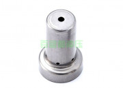
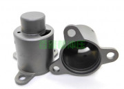
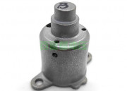
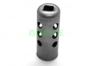
Zhejiang Balford Mechatronics Co., ltd focus on difficult stamping & deep drawing. Main product: motor housing and difficult custom deep drawn stampings.

  • What are the common quality problems of stamping and drawing parts processed by stamping dies?

    By : Categories : Balford News,Blog,Industry Comment: Comments Off on What are the common quality problems of stamping and drawing parts processed by stamping dies?

    1. During the stretching process of the wrinkled material, the tangential stress of the surrounding edge part is too large, which causes the instability of the material and causes the product to form uneven wrinkles along the tangential direction of the edge, which is called wrinkling. When the wrinkling is serious, it will also cause the material to be difficult to pass through the gap between the die and the punch during the stretching process, the tensile deformation force will increase, and even lead to cracking. The occurrence of buckling depends not only on the tangential stress at the edge of the material, but also on the thickness of the tensile member. Generally speaking, the stretching die using nitrogen gas spring or excellent release glue has better effect, and it is not easy to appear wrinkling, cracking and other phenomena. Why? Since the force of the nitrogen gas spring or super glue is generally balanced, there is no problem of uneven force. Nitrogen gas springs are better than Uniglue, because the nitrogen springs have strong force and good balance, but the price is several times more expensive than Uniglum, and many factories cannot afford them. Generally, only slightly larger factories can afford to use gas springs. If you use it for a long time, the super glue will shrink and its strength will not be as strong as it used to be. You’ll have to get a new one, but it’s a lot less expensive than a gas spring. The blank holder ring can be used to prevent wrinkling. In some places, it is called a pressing rib, which means that a circle of raised ribs is placed around the material without affecting the post-processing of the product, commonly known as a pressing rib, to press the material. Around. The advantage of this is that the stretched product will be fuller and will also prevent wrinkling.

    The blank holder force needs to be relatively adjusted in the mold test. The general design is not so reasonable, and the height of the blank holder needs to be adjusted appropriately according to the specific conditions of the product. If the blank holder force is too large, the friction between the material and the die and the blank holder ring will increase, which will make the material wall thinner or even cracked; if the blank holder force is too small, it cannot effectively prevent wrinkling. .

    Second, the second problem is pulling crack, which is a problem often encountered in the stretching process. When the tensile stress on the cylinder wall exceeds the strength limit of the material, the product will crack, and the crack generally occurs at the cylinder wall slightly above the punch fillet.

    The factors that affect the deep drawing crack of the product are: the tensile properties of the material, the diameter and thickness of the material, the drawing coefficient, the fillet radius of the concave and convex die, the blank holder force, the friction coefficient, etc. The radius of the rounded corner of the concave and convex die is too small and too sharp, which is easy to cause the product to crack. The general mold repair method is to find a way to increase the rounded corner to make the rounded corner smoother and brighter. Yes, especially stretching oils, are very effective. When designing the stamping die, you can enlarge the fillet as far as the customer’s product allows. Don’t make it too sharp. Some designs are not well understood. The designed drawing die cracked very badly during the die test, and wanted to exhaust the fitter. what! Repairing molds is annoying.

    The use of necessary lubricants during stretching is conducive to the smooth progress of the stamping and stretching process and improves the thinning degree of the cylinder wall. But it must be noted that the lubricant can only be applied to the working surface of the die, and cannot be lubricated on the contact surface of the punch and the material, because the punch and the blank surface are a kind of favorable friction, which can prevent Material slips, cracks and thins.

    Read More →
  • What are the points of attention for the design of precision drawing molds during the processing and production of drawing parts?

    By : Categories : Blog,Industry,Techniques Comment: Comments Off on What are the points of attention for the design of precision drawing molds during the processing and production of drawing parts?

    First, the shortcomings of the current upward continuous stretching die.

    1. The thickness of the template is not uniform. The key to the stretching die is the stripping plate, which should be thickened and the splint should be appropriately thinned.

    2. The guide gap of the drawing die is large, the die and the guide post, especially the stripper plate and the guide post, the gap between the punch and the guide post is large, and the precision of the guide post is poor.

    3. The choice of the spring is not very reasonable. The key to the stretching die is the blank holder, and it is necessary to ensure that the stretching cannot be wrinkled.

    Precision Drawing Die

    2. What should be paid attention to when the continuous stretching die is stretched upward?

    1. Thickness of the template: Because the upper mold needs to be equipped with a spring or a nitrogen gas spring, the upper cover plate is 25mm thick as far as possible, and the upper foot is determined according to the height of the stretched product and the cover degree of the spring required.

    2. Upward stretching is actually a very critical point. It is a product orientation problem, especially for products with high stretching. It is easy to deform during the stretching process. If the product is crooked, it is difficult to guide. Then every step of stretching The question of orientation is the key.

    3. Clearance: stretch upward, the inner guide should be neutral as far as possible, fixed on the stripper plate, which is conducive to disassembly. Colleagues use ball guide posts, which rely on the rotation of the ball to slide, so that the guiding accuracy can be guaranteed.

    4. Selection of springs: D. A group of trimming generally chooses springs that can be stripped. At the beginning, the upper springs need to bear the stretching effect, so nitrogen gas springs are required. According to the product material and the size of the material, the thickness of the material must be Choose different tonnages, try not to choose large ones, because the blanking plate needs to arrange at least 4 springs. Not only that, but also different colors of springs need to be selected according to the thickness of the material and the diameter of the material. The subsequent stretching is based on a principle that the lower spring is smaller than the upper spring, and the lower spring can be stripped.

    The continuous mold production process adopted by Baifudu Electromechanical Stamping, multiple processes are completed in the same mold, and the one-time molding of the product is realized. The precision of the finished product is higher and the quality is more stable. It can produce various stainless steel tensile parts, Drawing shells, stamping deep drawing parts, metal deep drawing parts, shell drawing parts, etc., what are the points to pay attention to in the design of precision drawing molds during the processing and production of drawing parts. The relevant content is as above, I hope it can help you.

    Read More →
  • Nitrogen Oxygen Sensor Housing

    By : Categories : deep drawing,deep drawn stainless steel Comment: Comments Off on Nitrogen Oxygen Sensor Housing

    Nitrogen Oxygen Sensor Housing

    1. Manufacturing process: stainless steel coil, deep drawing, deep drawing, redrawing, flat head chamfering

    2. Scope of application: Mazda car nitrogen oxygen sensor shell cover is universal

    3. Stamping material: stainless steel 316

    4. Surface treatment: ultrasonic oxyhydroxide cleaning

    5. Size specifications: The size can be customized according to your company’s requirements, and the unit price is negotiable.

    6. Product features: no burrs on the end face, flat head chamfering, parallel and vertical cut surfaces, bright appearance

    7. Quality: The production quality is strictly controlled, and the products are fully inspected before they are shipped. The products must be inspected before leaving the factory to ensure that every process meets the requirements and quality problems.

    Quality comes from details. In order to let you buy better products, we strive to improve every detail. From accessories to craftsmanship, we are devoted to the pursuit of quality by Balford people.

    Read More →
  • ford volvo fuel pressure valve deep drawing housing scv valve housing

    By : Categories : deep drawing,deep drawn low carbon steel Comment: Comments Off on ford volvo fuel pressure valve deep drawing housing scv valve housing

    ford volvo fuel pressure valve deep drawing housing scv valve housing

    1. Manufacturing process: pure iron coil, deep drawing, deep drawing, redrawing, extruding steps, punching top holes, punching side holes

    2. Scope of application: Ford Volvo, Weichai Xichai Bosch, GM Chevrolet common rail high pressure fuel pressure valve, solenoid valve

    3. Stamping material: pure iron dt4e

    4. Surface treatment: rust removal, oil removal, galvanized nickel alloy

    5. Dimensions: Outer diameter is 31.5, inner diameter is 17.4, and height is 44.8. In addition, the dimensions can be customized according to your company’s requirements, and the unit price is negotiable.

    6. Product features: there is no burr on the end face, the cut surface is parallel and vertical, and the appearance is bright

    7. Quality: The production quality is strictly controlled, and the products are fully inspected before they are shipped. The products must be inspected before leaving the factory to ensure that every process meets the requirements and quality problems.

    Quality comes from details. In order to let you buy better products, we strive to improve every detail. From accessories to craftsmanship, we are devoted to the pursuit of quality by Balford people.

    Read More →
  • Bosch EFI system fuel flow 818 metering unit housing

    By : Categories : deep drawing,deep drawn low carbon steel Comment: Comments Off on Bosch EFI system fuel flow 818 metering unit housing

    Bosch EFI system fuel flow 818 metering unit housing

    1. Manufacturing process: pure iron coil, deep drawing, deep drawing, redrawing, extruding steps, trimming, punching, leveling

    2. Scope of application: Bosch EFI system fuel solenoid valve, fuel flow metering unit, 818 model

    3. Stamping material: pure iron dt4e

    4. Surface treatment: rust and oil removal galvanized nickel alloy

    5. Dimensions: Outer diameter 31.4, inner diameter 27.5, height, 50.8. In addition, the dimensions can be customized according to your company’s requirements, and the unit price is negotiable.

    6. Product features: no burrs on the end face, bright appearance

    7. Quality: The production quality is strictly controlled, and the products are fully inspected before they are shipped. The products must be inspected before leaving the factory to ensure that every process meets the requirements and quality problems.

    Quality comes from details. In order to let you buy better products, we strive to improve every detail. From accessories to craftsmanship, we are devoted to the pursuit of quality by Balford people.

    8. Supporting products: oil filter sleeve, magnetic shield

    Read More →
  • Stamping die design method and operation steps are introduced in detail

    By : Categories : Blog,Techniques Comment: Comments Off on Stamping die design method and operation steps are introduced in detail

    1. Analysis of stamping process of stamping parts

    Stamping parts must have excellent stamping process, so that qualified stamping parts can be produced in the simplest and most economical way, and the process analysis of stamping can be completed according to the following methods:

    1. Be able to read the part drawing: In addition to the shape and size of the part, the key points are to understand the requirements of the part accuracy and surface roughness.

    2. Analyze whether the structure and shape of the parts are suitable for stamping processing.

    3. Analyze whether the benchmark selection and size marking of parts are reasonable, and whether the accuracy of size, orientation and shape is suitable for stamping processing.

    4. Whether the rough surface requirements of the blanking section are too high.

    5. Whether there is a strong enough production batch.

    If the craftsmanship of the part is too poor, the planner should be communicated and a plan to revise the plan should be proposed. Assuming the production batch size, other production methods should be considered for processing.

    2. Stamping process planning and best process design.

    1. According to the shape and size of the stamping parts, start to judge the nature of the stamping process, such as punching, bending, deep drawing, bulging, reaming and other stamping die planning methods and processes.

    2. Calculate the degree of deformation of each stamping method. If the degree of deformation exceeds the limit deformation degree, the number of punches for the process should be calculated.

    3. According to the deformation characteristics and quality requirements of each process, organize a reasonable stamping sequence. Care should be taken to ensure that the deformation area of ​​each process is a weak area, and the formed parts (including punched holes or shapes) must not participate in deformation in subsequent processes. Polygonal zigzag parts should be bent first and then bent inward, and necessary auxiliary processes and processes such as shaping, leveling, and heat treatment should be organized.

    4. On the premise of ensuring the accuracy of the parts, according to the production batch and the blank positioning and unloading requirements, determine a reasonable process combination method.

    5. More than two process plans should be planned, and the best process plan should be selected from the aspects of quality, cost, productivity, mold sharpening and repair, mold life, operation safety, etc.

    6. Start to judge the stamping equipment of each process.

    3. Blank planning and layout drawing design of stamping parts

    1. According to the performance scale of stamping parts, calculate the blank size and make a blank drawing

    2. According to the roughness scale, plan the layout drawing and calculate the data utilization rate. To plan a variety of nesting plans, choose the best plan by comparison.

    Fourth, die design

    1. Determine the die structure method of each process of stamping processing, and make a schematic diagram of the die.

    2. Carry out specific structural planning for the 1-2 processes specified by the mold, and make the mold operation diagram. The planning method is as follows:

    (1) Determine the type of mold: whether it is a simple mold, a continuous mold or a composite mold.

    (2) Design of mold working parts: Calculate the size of the edge of the convex and concave molds and the length of the convex and concave molds, and determine the structure and connection and fixing methods of the convex and concave molds.

    (3) Determine the positioning and spacing method of the blank, and plan the corresponding positioning and spacing parts.

    (4) Determine the pressing, unloading, ejecting and pushing methods, and plan the corresponding pressing plates, unloading plates, and pushing blocks.

    (5) Formwork design: It includes the design of upper and lower die bases and guiding methods, and standard formwork can also be selected.

    (6) On the basis of completing the above operations, make a mold operation diagram according to the scale. First make blanks with double-dot-dash lines, then make parts, then make positioning and spaced parts, connect the above parts with connecting parts, and finally make pressing and unloading parts in the proper position. According to the specific conditions of the mold, the above order can also be adjusted appropriately.

    (7) The outer contour size of the mold, the closed height of the mold, the cooperation size, and the design method and process mold design of the cooperation type stamping die should be marked on the work map. The job drawing should indicate the requirements of the production accuracy and skill conditions of the mold. The job drawing should be made according to the national drawing standards, with a standardized title bar and detailed table. If it is a blanking die, make a layout drawing on the upper left corner of the work drawing.

    (8) Calculate the pressure center of the mold and check whether the pressure center coincides with the center line of the mold handle. If they do not coincide, make corresponding corrections to the mold results.

    (9) Calculate the punching force, finally select the punching equipment, and check the relevant dimensions of the die and the punching equipment (closed height, work surface, die handle device dimensions, etc.).

    Read More →
  • What are the design and material requirements for precision stamping parts?

    By : Categories : Blog,Industry Comment: Comments Off on What are the design and material requirements for precision stamping parts?

    Precision stamping and ordinary stamping are completely different. The minimum value of the hole diameter and hole margin of precision stamping parts is smaller than that of ordinary stamping. Therefore, when designing precision stamping parts, there are certain requirements for the design of the structure.

    When designing the structure of precision stamping parts, the shape of the workpiece and the inner hole should be rounded, and sharp corners are not allowed. However, the minimum allowable corner radius value is related to the material thickness. The punching diameter, slot width and edge distance of the workpiece should not be too small. When precision stamping gears, the pitch circle tooth width of the gear should not be less than 0.6T, and the top and root of the tooth shape should be a rounded transition, not a sharp transition. The contour shape of the outer edge of precision stamping parts should be as smooth as possible, and should not change suddenly. On the surface of the workpiece, design symbols or marks, and when pressing, the cutting depth should not exceed 0.25T.

    In general, the production of precision stamped workpieces is mainly based on strong blanking and fine blanking. The geometry, dimensional tolerances, geometric tolerances and shear surface quality of fine blanked workpieces are much higher than those of ordinary blanked workpieces.

    The most commonly used materials in the production of precision stampings are metallic materials (including ferrous and non-ferrous metals), but sometimes non-metallic materials are also used.

    Among them, ferrous metals mainly include ordinary carbon structural steel, high-quality carbon structural steel, alloy structural steel, carbon tool steel, stainless steel, electrical silicon steel, etc.; non-ferrous metals mainly include pure copper, brass, bronze, aluminum, etc.; there are many Metal materials and models. How can we choose materials, not only to ensure the quality of the workpiece, but also save materials?

    When manufacturers of precision stamping parts choose stamping materials for drawing parts, they generally have the following principles:

    Metal materials must meet the performance requirements of the workpiece; stamping parts work normally in machines or parts and have a certain service life.

    The selected material must have good process performance; for any kind of stamping part, the selected material should be able to meet the requirements of the stamping process.

    The selected material should have good economy; under the premise of meeting the performance and stamping process requirements, the material should be low in price, convenient in source and economical to reduce the cost of stamping parts.

    The above are the principles that manufacturers of precision metal stamping parts should follow when choosing metal stamping materials. Hope the above content is helpful to readers.

    Read More →
  • What are the common problems in the production of stamping and drawing parts?

    By : Categories : Blog,Techniques Comment: Comments Off on What are the common problems in the production of stamping and drawing parts?

    1. The reason for the instability and wrinkling of the flange of the stretched part: the blank holder force is too small, or the relative thickness of the blank is small, or the tensile coefficient is too small.

    Solution: Increase the blank holder force or increase the number of stretches.

    2. Reasons for surface strain of stamping and drawing parts: low heat treatment hardness, poor finish, improper material selection, excessive material thickness, wear of concave die fillet, poor surface quality of bending blank, unreasonable selection of process plan, insufficient lubrication, etc.

    Solution: For stamping parts that need to be stretched many times, under the premise of ensuring the necessary appearance quality, there are traces that can occur during the stretching process. Choose suitable materials and process solutions, lubricate and reduce friction.

    3. Reasons for the inconsistent shape and size of stamping and drawing parts: due to inaccurate positioning, in addition to taking measures to reduce springback, the reliability of blank positioning should also be improved.

    Solution: The shape of stamping and drawing should be as simple and symmetrical as possible, and one-time stretching should be done as much as possible.

    4. The reason for the cracking of the hole after the stretching of the tensile member with the hole: the hole diameter is too large, so that the material around the hole is subjected to a large tensile stress, which leads to fracture.

    Solution: Change the sequence of forming process, stretch and form first, and then punch holes at the bottom.

    5. The reason for the instability and wrinkling of the upper edge of the cylindrical drawing part: the radius of the concave die fillet is too large, which causes the gap between the concave die and the punch die to be too large, or the blank holder force is too small.

    Solution: increase the blank holder force and reduce the radius of the die fillet.

    In the drawing process, the cylindrical drawing part is a common metal drawing part, which is widely used. Some customers have special requirements for stretched parts, such as flanging, etc., which can meet the special requirements of the product. Drawing parts processing plants need to fully understand the knowledge of drawing parts flanging processing.

    Cylindrical stretching parts with flanging include narrow flanging, cylindrical stretching parts and wide flanging cylindrical stretching parts; narrow flanging cylindrical punching and stretching parts are stretching parts with a small total flange width . When this type of parts is stretched many times, due to the narrow flanging, it can be stretched by punching the flanging cylinder first, and then the flanging process is performed to form the specified narrow flanging shape.

    In order to make the flanging better, the conical concave die and the conical pressing ring can be selected for stretching in the last two processes of drawing, and the conical flanging can be vacated, so that the flanging area can be reduced when the part is formed. Radial tensile deformation is beneficial to avoid edge cracking.

    When the wide-flanged cylindrical stretched piece needs to be stretched multiple times, for the first stretch, make sure that the flanging specification is equivalent to the flanging specification of the stretched piece. In the next stretching, the flanging specification No change, only the raw material in a certain part of the cylinder migrates to the stretch specification. Because in the subsequent stretching process, even a small deformation caused by a part of the flanging will cause a very large tensile stress in the force transmission area of ​​the cylinder wall, thereby causing the bottom section to crack.

    Read More →
  • What are the reasons for the uneven appearance of stamping parts?

    By : Categories : Blog,Industry Comment: Comments Off on What are the reasons for the uneven appearance of stamping parts?

    1. There is no air hole on the punch.

    During the stamping process, the air in the workpiece is compressed by the punch and cannot be discharged, which makes the shape of the drawn part uneven, which is often ignored by many people. The solution is to add air vents on the punch.

    Second, the blank is uneven.

    The rough surface is uneven, resulting in an uneven surface of the drawn part. The solution is to replace the material with a better surface quality.

    Processing stamping and drawing parts

    Third, the material rebounds greatly.

    The material has a large springback, resulting in an uneven appearance of the drawn part. The solution is to increase the annealing or shaping process.

    Fourth, the gap between the punch and the die is too large.

    If the gap is too large, the working surface of the mold will lose its straightening effect on the wall of the workpiece, making the shape of the workpiece uneven. Therefore, the die gap should be trimmed or replaced with new parts.

    5. The negative deviation of material thickness is too large.

    If the material thickness is too small, the gap between the molds will be larger, making the appearance uneven. The material needs to be replaced with a suitable thickness.

    6. Improper use of stretching oil.

    Select the correct stamping and drawing oil to ensure effective lubrication during the drawing process. Deep drawing processes require extreme pressure lubricants and highly effective antiwear agents. Mineral oil is generally not suitable. Stamping and drawing oil is prepared by adding oily agent, extreme pressure agent, anti-wear agent and synthetic ester. The products are widely used in calendering forming processes such as automobile panels, doors and trunks, and calendering forming processes such as carbon steel and sheet metal. It can effectively reduce the friction between the workpiece and the mold, reduce wear and tear, and the oil film is firm. It can effectively reduce the occurrence of marks, scratches, sintering welding, cracking and other phenomena. It helps the metal to slide, is conducive to forming, has no jamming, and ensures that the edge of the workpiece is smooth and free of burrs. It has good thermal stability at high temperature. Good smooth function, improve machining accuracy, protect mold, prolong mold life.

    When processing metal stamping and drawing parts, if there is an uneven appearance, you may first find out the reasons from the above aspects.

    Read More →
  • What are the common materials in the production of stamping and drawing parts?

    By : Categories : Blog,Industry,Techniques Comment: Comments Off on What are the common materials in the production of stamping and drawing parts?

    1. Stainless steel stamping and drawing parts

    Stainless steel tensile parts have the characteristics of high strength, light weight, good wear resistance, and high corrosion resistance. The tensile parts of this material do not require electroplating protection. It is suitable for heat treatment and is often used in fuel systems, braking systems, exhaust systems, oxidation sensors and decorative parts in automobile manufacturing.

    2. Low carbon steel stamping and drawing parts

    Low carbon steel has the characteristics of excellent formability, stable forming dimensions, high strength, and light weight (see material grade for details). It is often used in various parts in automobile manufacturing, especially high-strength mechanism parts.

    3. Aluminum alloy stamping and drawing parts

    The characteristics of aluminum alloy tensile parts are: light weight (almost 1/3 of low carbon steel), high strength, non-magnetic, stainless rust, anodized anti-corrosion, suitable for heat treatment, etc., and are often used in bulk in automobile manufacturing and other industries. devices, energy storage devices, beverage containers and the pharmaceutical industry.

    4. Copper alloy tensile parts

    Copper alloy drawing parts have the characteristics of stable forming dimensions, corrosion resistance, good ductility, and easy welding. The disadvantage is that they are easy to oxidize. Due to the high price of copper alloy materials, waste needs to be reduced and recycled if necessary.

    The above is related to the processing materials of stamping and drawing parts. In general, the machining methods for machining parts from different materials will vary. Material properties and processing characteristics should be considered to avoid losses. Hope the above content is helpful to readers.

    Read More →
  • Exhaust Emission Sensor Housing Automotive Exhaust Temperature Sensor Housing

    By : Categories : deep drawing,deep drawn stainless steel Comment: Comments Off on Exhaust Emission Sensor Housing Automotive Exhaust Temperature Sensor Housing

    Exhaust Emission Sensor Housing Automotive Exhaust Temperature Sensor Housing

    1. Manufacturing process: stainless steel coil, deep drawing, deep drawing, redrawing, shaping, flat head, groove, top hole, side hole

    2. Scope of application: Volkswagen exhaust temperature sensor connecting pipe protective sleeve is universal

    3. Stamping material: stainless steel 310s high heat-resistant stainless steel

    4. Surface treatment: polishing and cleaning

    5. Size specifications: outer diameter 7 inner diameter 6, height 16, there are many styles, in addition, the size can be customized according to your company’s requirements, and the unit price is negotiable.

    6. Product features: There are no burrs on both ends, no inner and outer chamfers, the cut surfaces are parallel and vertical, and the appearance is bright

    7. Quality: The production quality is strictly controlled, and the products are fully inspected before they are shipped. The products must be inspected before leaving the factory to ensure that every process meets the requirements and quality problems.

    Quality comes from details. In order to let you buy better products, we strive to improve every detail. From accessories to craftsmanship, we are devoted to the pursuit of quality by Balford people.

    Read More →
  • Chevrolet car exhaust temperature sensor protection tube exhaust temperature sensor housing

    By : Categories : deep drawing,deep drawn stainless steel Comment: Comments Off on Chevrolet car exhaust temperature sensor protection tube exhaust temperature sensor housing

    Sinotruk exhaust exhaust temperature sensor upper cover

    1. Manufacturing process: stainless steel coil, deep drawing, deep drawing, redrawing, shaping, flat head, groove, top hole, side hole

    2. Scope of application: Chevrolet GM, Sinotruk, Jiefang Xichai Yuchai Weichai exhaust temperature sensor connecting pipe protective sleeve

    3. Stamping material: stainless steel 310s, high temperature resistant stainless steel

    4. Surface treatment: polishing and cleaning

    5. Dimensions: Outer diameter 7, inner diameter 6.35, height 24.5, other dimensions can be customized according to your company’s requirements, and the unit price is negotiable.

    6. Product features: There are no burrs on both ends, no inner and outer chamfers, the cut surfaces are parallel and vertical, and the appearance is bright

    7. Quality: Strictly control the production quality, the products are fully inspected before they are shipped, and the products must be inspected before leaving the factory to ensure that every process meets the requirements and quality problems.

    Quality comes from details. In order to let you buy better products, we strive to improve every detail. From accessories to craftsmanship, we are devoted to the pursuit of quality by Balford people.

    Read More →
  • Car Wuling water temperature sensor copper shell water temperature plug shell

    By : Categories : deep drawing,deep drawn brass Comment: Comments Off on Car Wuling water temperature sensor copper shell water temperature plug shell

    Car Wuling water temperature sensor copper shell water temperature plug shell

    1. Manufacturing process: brass coil, deep drawing, deep drawing, redrawing, extruding steps, flat head chamfering

    2. Scope of application: Wuling Automobile, Sinotruk, Jiefang Xichai, Yuchai, Weichai water temperature sensor copper shell outer cover universal

    3. Stamping material: brass h65

    4. Surface treatment: special degreaser for copper, special brightener for copper, special color retention agent for copper

    5. Dimensions: Outer diameter 18, inner diameter 17.15, height 27.5, in addition, the dimensions can be customized according to your company’s requirements, and the unit price is negotiable.

    6. Product features: no burrs on the end face, flat head chamfering, parallel and vertical cut surfaces, bright appearance

    7. Quality: The production quality is strictly controlled, and the products are fully inspected before they are shipped. The products must be inspected before leaving the factory to ensure that every process meets the requirements and quality problems.

    Quality comes from details. In order to let you buy better products, we strive to improve every detail. From accessories to craftsmanship, we are devoted to the pursuit of quality by Balford people.

    Read More →
  • How to extend the service life of stamping and drawing parts?

    By : Categories : Balford News,Blog Comment: Comments Off on How to extend the service life of stamping and drawing parts?

    1. How to prolong the service life of stamping and drawing parts?

    1. After the stamping and drawing parts are installed and used, the stamping parts must be strictly inspected, the dirt must be removed, and the guide sleeves and molds of the stamping parts must be carefully checked whether they are well lubricated.

    2. Install the mold on the turntable according to the installation steps of the mold to ensure that the direction of the mold and the mold is consistent, especially the direction (non-circular and square) required for the stamping part is larger. Take care to prevent assembly errors and backlash.

    3. When the punch of the stamping part and the edge of the die are worn, it should be stopped in time for grinding. Otherwise, the wear degree of the die edge will expand rapidly, the die wear will be accelerated, and the quality of stamping parts and die life will be reduced.

    4. Regularly check the punch turntable and die mounting seat to ensure the coaxial accuracy of both sides of the turntable.

    5. When the mold is installed, softer metals (such as copper, aluminum, etc.) should be used to make operating tools to avoid damage to the drawing parts during the installation process.

    The mold structure is reasonable, the manufacturing precision is high, the heat treatment effect is good, the punch selection of the deep drawing parts is correct, the installation accuracy is high, and the correct use, maintenance and maintenance of the mold are also important factors. Therefore, it is necessary to eliminate the adverse effects of various factors on the service life of tensile stamping parts, and take effective measures to improve its service life.

    In the production process of stretched parts, there will be many bad problems. Next, we analyze these issues.

    Second, the common bad problems in the production process of tensile parts

    1. The effect of stretching depth

    The distribution of the flow resistance of the drawn material along the die is directly related to the drawing depth. Above the position of the inner concave and outer convex curves, the drawing depth of the stretcher is too large, resulting in uneven distribution of deformation resistance and wrinkling, which should be avoided as much as possible.

    2. Adjust the blank holder force

    When the wrinkles around the part appear evenly, it should be judged that the pressing force is insufficient, and the pressing force can be gradually increased to remove it. When the tensile part stretches the conical part and the hemispheric part, most of the data is in the suspended state. The side wall is prone to wrinkling, so in addition to increasing the blank holder force, the precision stamping parts processing plant should also choose to increase the pick-up rib to increase the radial tensile stress in the sheet, thereby eliminating wrinkling.

    3. The influence of the radius of the die fillet

    If the radius of the fillet of the die of the drawing part is too large, the flow of the blank into the die through the fillet of the die is the smaller the tortuous resistance of the tortuous deformation. The smaller the tortuous resistance, the easier it is to cause wrinkling to occur. The smaller the radius of the die, the greater the bending resistance of the bending deformation, and the less likely it is to wrinkle, but it is easy to cause cracking and hair pulling of the stretched parts.

    The main reasons for the wrinkling of the stretched parts obtained through a lot of practical experience in production are the accumulation of materials during the stretching process and the excessive speed of local material movement. When formulating a solution, the precision stamping parts processing plant should consider and adjust the corresponding structure of the mold from the perspective of more than one aspect, which will get a good effect.

    The above is the relevant content about the service life and defects of stamping and drawing parts. Stamping and drawing parts are widely used in daily life. In order to properly prolong the service life of stamping and drawing parts, we also need careful maintenance. Hope the above content is helpful to readers.

    Read More →
  • What are the types of metal stamping and drawing parts?

    By : Categories : Blog,Techniques Comment: Comments Off on What are the types of metal stamping and drawing parts?

    Stamping and drawing parts” width=”613″ height=”403″ border=”0″ vspace=”0″ title=”Metal stamping and drawing parts” style=”max-width:100%!important;height:auto! important;width: 613px; height: 403px;”/>

    Stamping equipment is used for drawing and forming of products, including drawing, redrawing, reverse drawing and thinning.

    Drawing processing: Using the platen device and the punching force of the punch, part or all of the flat plate is pulled into the cavity of the female die to form a bottomed container. The sidewall of the container is processed parallel to the drawing direction, and the deep drawing processing of conical (or pyramidal) containers, hemispherical containers, and parabolic containers also includes expansion processing.

    Re-drawing: For deep-drawn products that cannot be completed by one-time drawing, the formed product needs to be re-drawn to increase the depth of the formed container.

    Reverse drawing processing: The drawing workpiece of the previous process is reversely drawn, and the inner side of the workpiece becomes the outer side, making its outer diameter smaller.

    Thinning and drawing processing: The forming container is squeezed into the concave mold cavity slightly smaller than the outer diameter of the container through the punching machine, so that the outer diameter of the bottomed container is smaller and the wall thickness is thinner, which not only eliminates the wall thickness deviation, but also makes the container surface smooth. .

    When using stamping equipment for metal stamping and drawing, the following 16 types are included:

    1. Cylinder drawing

    Drawing of cylindrical products with flanges (flanges). The flange and the bottom are both plane shapes, the side wall of the cylinder is axisymmetric, the deformation is evenly distributed on the same circumference, and the blank on the flange is deep-drawing deformation.

    2. Elliptical drawing process

    The deformation of the blank on the flange is tensile deformation, but the deformation amount and deformation ratio change correspondingly along the contour shape. The greater the curvature, the greater the plastic deformation of the blank; conversely, the smaller the curvature, the smaller the plastic deformation of the blank.

    3. Rectangular drawing process

    A low rectangular piece formed by one stretch. During stretching, the tensile resistance at the rounded corners of the flange deformation zone is greater than that at the straight edge, and the degree of deformation at the rounded corner is greater than that at the straight edge.

    4. Yamagata drawing process

    When the side wall of the stamping part is inclined, the side wall is suspended during the stamping process, and the mold is not attached until the end of forming. The deformation characteristics of different parts of the sidewall during the forming process are not exactly the same.

    Read More →